Group Tasnim Biglari Maddah
Group members
Group Work Documentation
For week 3, we performed both group and individual work. Our group assignment was: 1. Perform your lab's safety training 2. Conduct tests to investigate power and speed settings, and the effect of focus, measure the kerf, and perform vector and raster tests
Vinyl Cutting
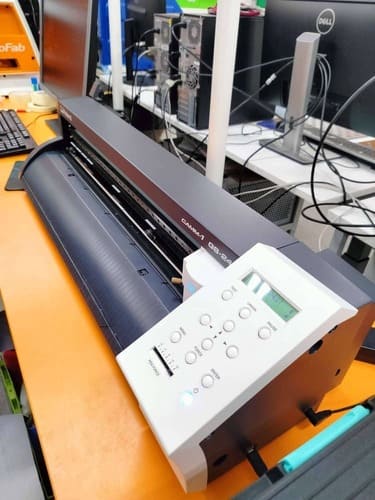
Behnaz showed us around the vinyl cutter, the multiple rolls of vinyl, and the settings for the device. The machine we used was the Roland CAMM-1 GS-24.
She used a blue piece of vinyl to cut a small heart on it. The design is imported from Inkscape to CutStudio, and then printed. After that, the sticker can be peeled off and the design transferred to a laptop or any object of your choice.
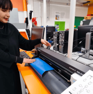
If you want to layer multiple pieces of vinyl to make a complex design, you need to use the UV machine to attach them together. You can also transfer the vinyl onto fabric, for which you would use the heat press machine and special vinyl rolls suitable for heat transfer.
Laser Cutting
Next we went on to learn about the laser cutting machine. The main device used in the lab is the Epilog Laser Fusion 75W CO2. Gleb showed us how to turn on the machine and then went through the laser safety procedure.
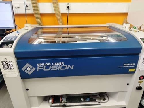
Setting up the Device
To turn the device on, you need to switch on the power button on the bottom right side of the device. Then you need to turn the air ventilation on. This is very important in order to get rid of the excess material that is being burnt away.
Once it is switched on, you can proceed to lift the cover and place any material of your choice. The Epilog Fusion is a pretty large device with a big working area, but for small projects it is always recommended to use small scrap materials to avoid waste.
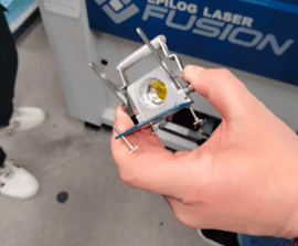
Next, we learned how to set up the device. Gleb pulled out the jog, which holds the laser, to show us how to keep the lens clean for the best results.
The control panel on the right side of the machine is used to set up the device for printing. We can use the arrows to choose the setting. Then we need to set the origin by moving the jog using the joystick. It is usually set on the top left corner of the material, making sure there is enough space for the design. The red pointer can be turned on to make it easier to see where the jog is pointing.
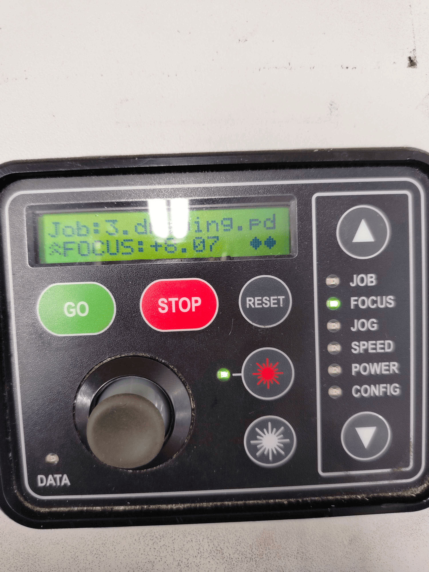
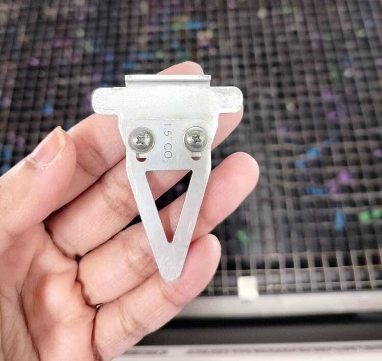
Next, we need to set the focus, which is the distance of the material from the laser. We place a triangular tool on the jog, then use the joystick to move the table up and down. The surface of the material needs to just touch the tip of the tool. Both settings can be saved by pushing the joystick.
Then we can choose Job from the settings and press Go to print our task.
Safety Procedures
For safety, Gleb emphasised the need to keep an eye on the device at all times while it is cutting. Any fires caused can easily be brought under control if we notice it immediately.
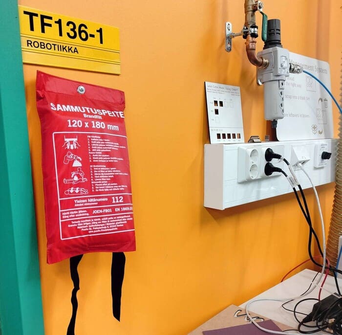
If a fire does occur, we have to turn off the device using the normal Stop button instead of the Emergency Stop button. A fire blanket is hung on the wall next to the device, which will be used to smother the fire. If the fire is out of control, there are other fire extinguishers around the lab. It is important to know their locations.
The reason the Emergency Stop button should not be used is that it will also turn off the ventilation system, causing build up of the waste materials.
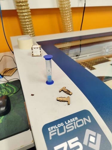
Laser cutting produces a lot of fine dust, and it needs time to be removed from the working area. Thus, it is important to keep the cover closed for at least one minute after a laser cutting job ends. To make this easier, next to the workstation, there is a small hourglass which we were instructed to turn around after a task. Only when all the sand has fallen should we open the cover.
Learning Tasks
To learn the basics of laser cutting, we performed a number of tasks under the guidance of Behnaz and Gleb.
1. Vector Test
First, we cut squares from a medium-density fibreboard (MDF), and used different power, speed, and frequency to test how they affect the cut.
Three types of results are possible with laser cutting:
- Engraving
- Scoring
- Cutting
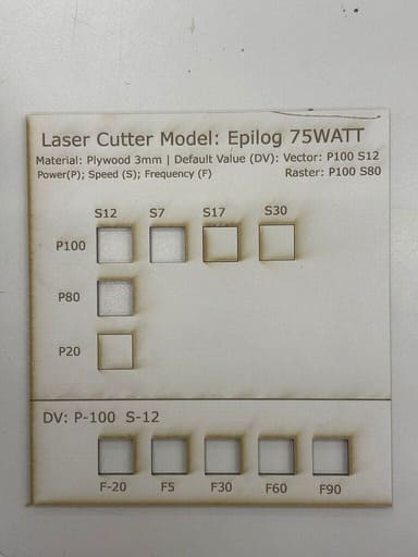
In the first row, we kept the power constant (100) while varying the speed. Both scoring and cutting took place. When the speed was the highest (30), the laser caused scoring on the material, while it cut the square with lower speed (12).
In the third row, with speed 12 but the power set very low, it caused scoring again.
In the last part of the task, we kept the speed and power constant while changing the frequency. This did not cause any visible changes in the cuts. However, it was explained by our instructor that higher frequency causes more burning. Changes in frequency produce visible changes in acrylic instead, where the sides of the cut area are smoother at higher frequency.
2. Kerf Test
With the next task, we experimented with kerf.
Kerf refers to the amount of material that is burned off during laser cutting.
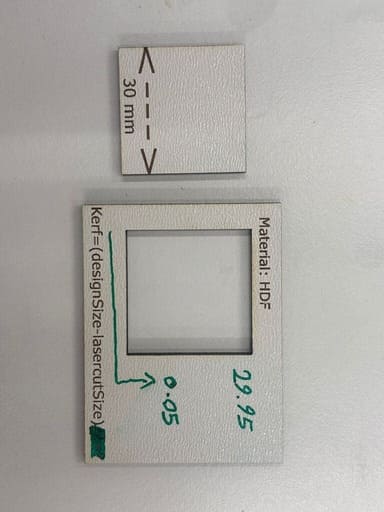
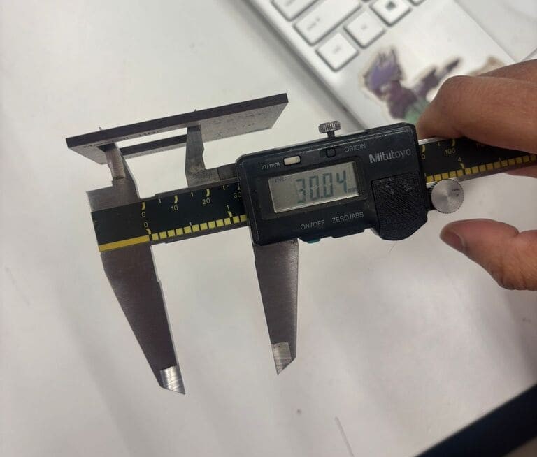
We cut a 30 mm square from an HDF material. After cutting, we used vernier callipers to measure the actual length of the cut square and the gap left in the original square.
We found the size of the square after the cutting to be 29.95 mm.
To measure the kerf, we used the formula:
kerf = design size − laser cut size
The kerf is 0.05 mm.
We also used the callipers to find the size of the gap to be 30.04 mm. The difference is because of the amount of material burnt away.
These measurements are important, especially when building press-fit kits where pieces need to slot into each other. For perfect fitting, the kerf needs to be taken into account.
Using these measurements, we proceeded to make some H-shaped pieces that can be slotted together. When preparing the files, we set the kerf measurements in the settings to be accounted for when cutting. This prevents the pieces from slotting in too tight or too loose.
We can account for kerf using the following formula:
slot width = material thickness - kerf
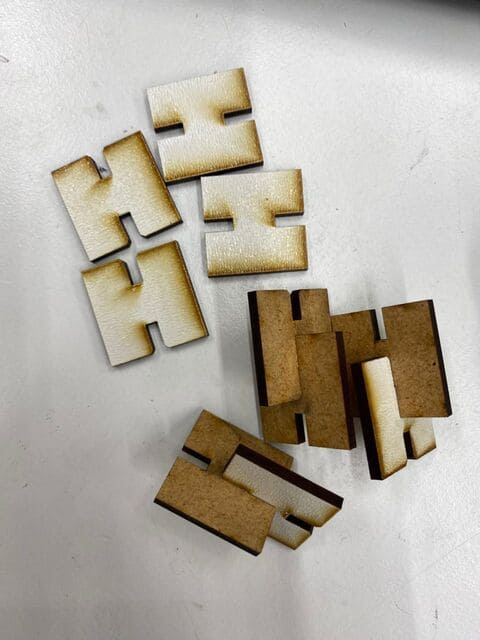
We made two of these pieces first to test how well they fit. They were too loose, so we adjusted the kerf measurement before printing more pieces. Later, it was found that the material was not exactly 3 mm in thickness, which resulted in skewed measurements.
3. LPC / DPI Test
For the next section, we used the high-precision XTool laser cutter machine.
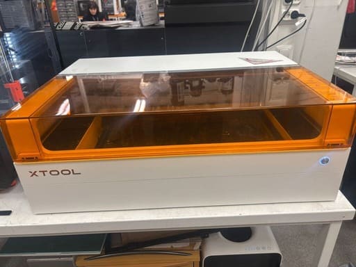
This device allows for changes in DPI (dots per inch). We wanted to test how the resulting engraving would be affected by the density of the laser.
In this device, the setting used is LPC (lines per centimeter). For each individual image, we set a different LPC ranging from 10 to 300.
The resulting pieces are as follows:
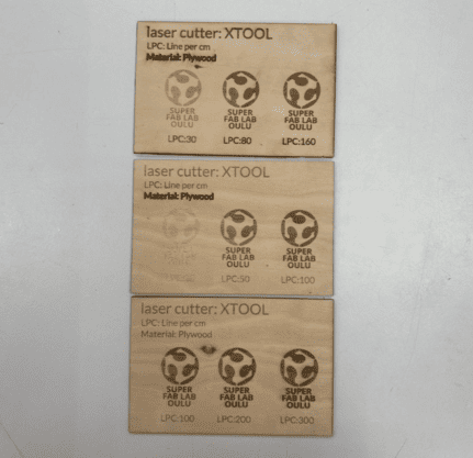
As we can see, the higher the LPC, the darker the engraving is. At 10 LPC, the image is barely visible.
4. Raster Test
In the fourth task, we tested the effect of different speed and power settings, as well as experimented with layers.
Each image was placed on a different layer, and the speed and power were set individually for each layer.
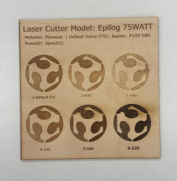
- In the first row, the speed was kept at a default of 80 while the power varied.
- In the second row, the power was kept at a default of 100 while the speed varied.
All the images were kept in the same file, but on different layers. To print them, all layers except the desired one were hidden and sent to print.
In the control panel of the laser cutter, when you select Job, you can see the names of the different files that have been sent. Using the joystick, you can move between the files and choose one to print.
As we can see from the image, with the lowest speed and highest power, the engraving is the darkest.
5. Focus Test
Finally, we tested the focus.
Focus depends on the distance of the table to the laser. The closer the table is, the higher the focus.
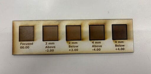
First, we started with the default focus, set to 00.00. Then we changed it to:
- 2 mm above
- 2 mm below
- 4 mm above
- 4 mm below
To change the focus, we used the joystick to adjust the height of the table.
The effects of different focus settings are shown below:
These teachings, especially the safety procedurs, were very important for performing future laser cutting projects.