Group1_nam
Group members
- Nam Nguyen
- Labeeb Zafar
- Siavash
- Nguyen Dinh
Input Devices
1. Distance sensor
First step is to setup power connection for the sensor so the VCC is connected to 3.3 V power supply and the GND is connected to GND on the XIAO RP2040.
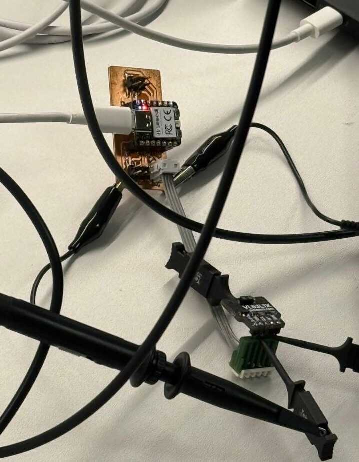
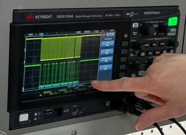
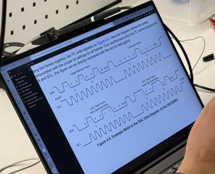
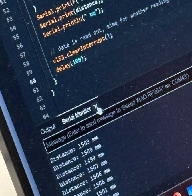
The teacher already prepared the code, so we just need to upload it to the XIAO RP2040. After flashing the code, we can see the distance value on the serial monitor. And we measure how data is transmitted through I2C communication. We placed the test probes on the SDA and SCL lines to observe the signal.
2. Potentiometer, thermistor, and photo transistor
The board below has 3 sensors and the board's schematic is shown below.
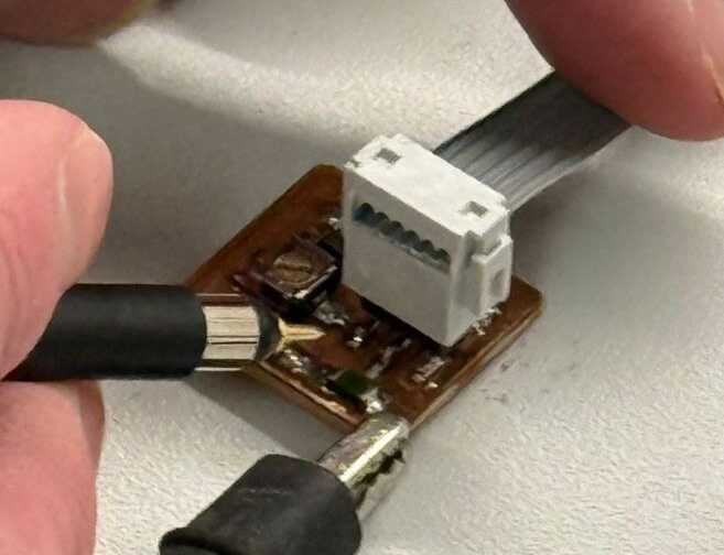
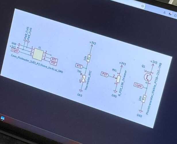
For the thermistor, when we warm it up with our hand, the voltage shows a drop. As sensor got warmer the signal drops.
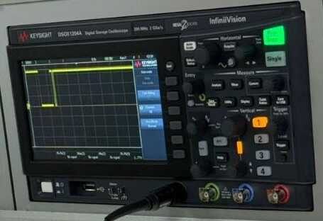
For the photo transistor, when we shoot very bright light on it, the voltage changes significantly, the voltage goes wildly up and down. However, we could not find any pictures about that measured signal.
For potentiometer, when we rotate it, the voltage changes smoothly and linearly. As we knew, when we rotate the potentiometer, the resistance changes and the voltage changes accordingly.