group1_nam
Group members
- {'name': None, 'url': None}
- {'name': None, 'url': None}
- {'name': None, 'url': None}
- {'name': None, 'url': None}
Electronic Production Week
This week we begin printing out our finalized design circuit board that we had made in KiCad.
Printing the PCB
Step 1: Before using the machine
To begin this process, we must first export our files as gerber files and transfer them to a USB stick so that it can be transferred to the PC that is connected to our PCB designing machine. Once all that is done, we can now begin the process.
Step 2: Setting up the machine
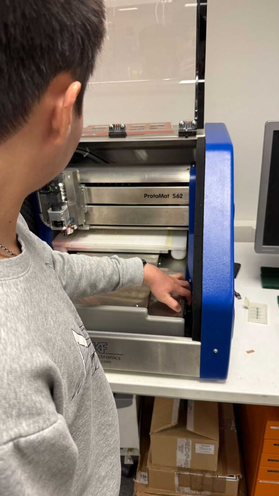
We first start by turning the machine on by pressing the button that is located on the right side inside the machine.
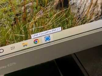
We then head to our computer and open the CircuitPro application so that we can begin setting everything up.
Once you launch this application you should see this as the default.
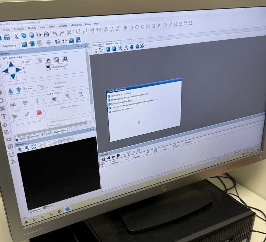
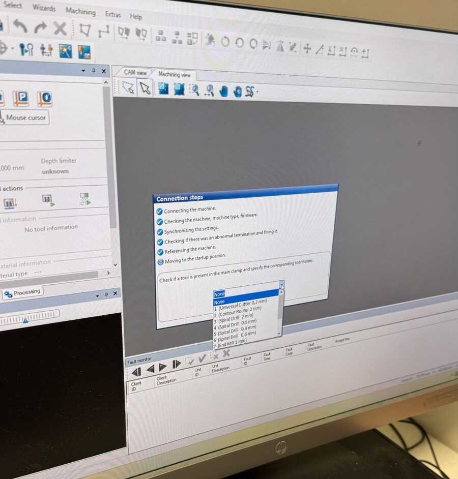
Then the application will show the warning below. This is used to check what tool is in the nozzle of the machine, based on what the previous user had left it as.
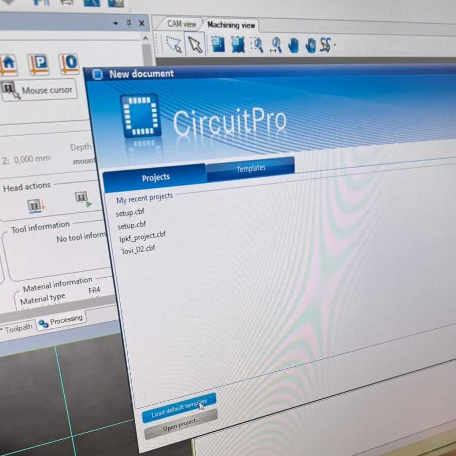
Then you are shown this menu where you can now open the templates that you originally imported.
Step 3: Buttons and their functions
Once you have opened the templates, you should have these options which are important to follow step by step.
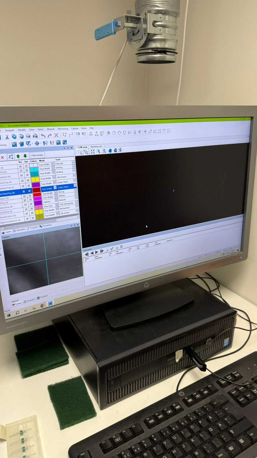
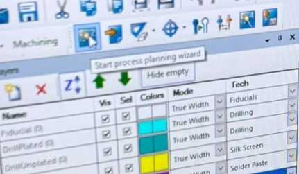
First button:
So, we click the first option as shown below. Then we go through all the options (see pictures).
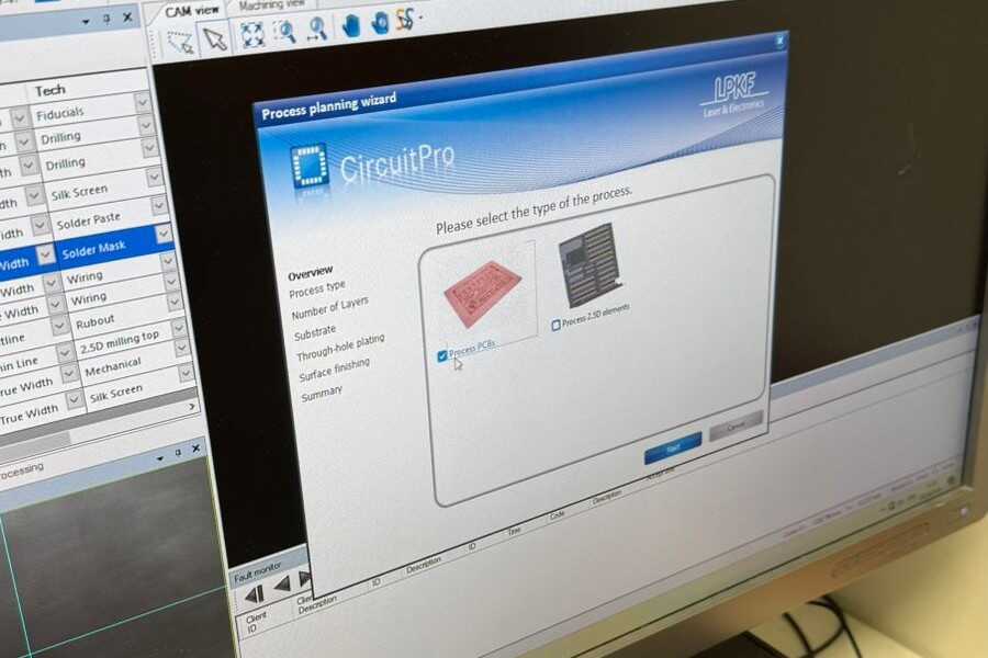
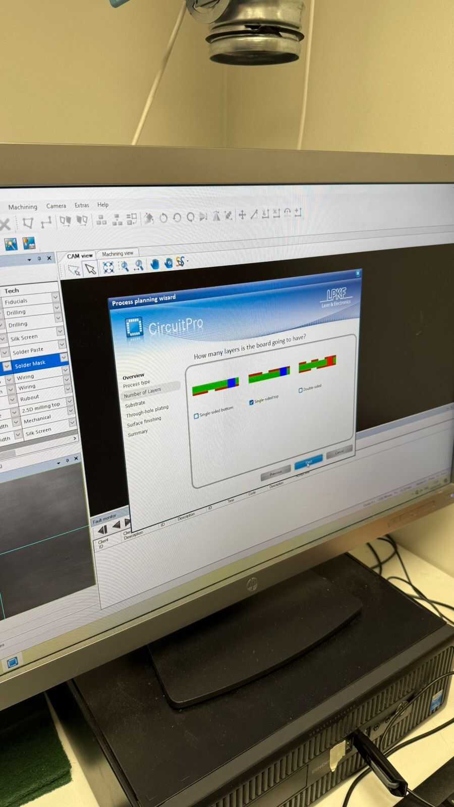
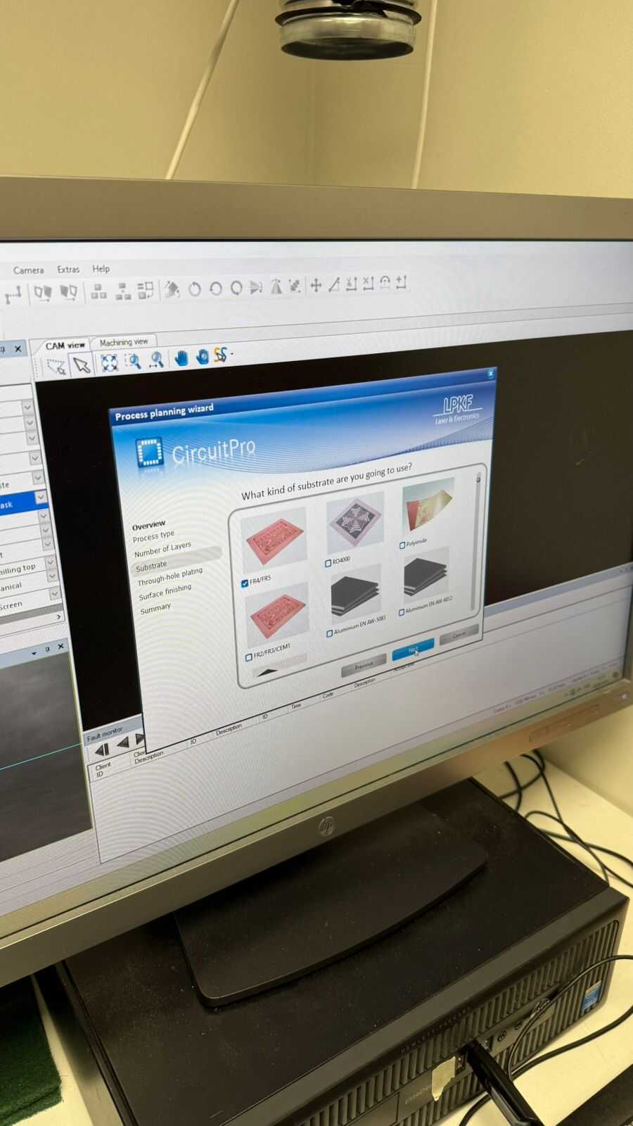
we use FR4/FR5
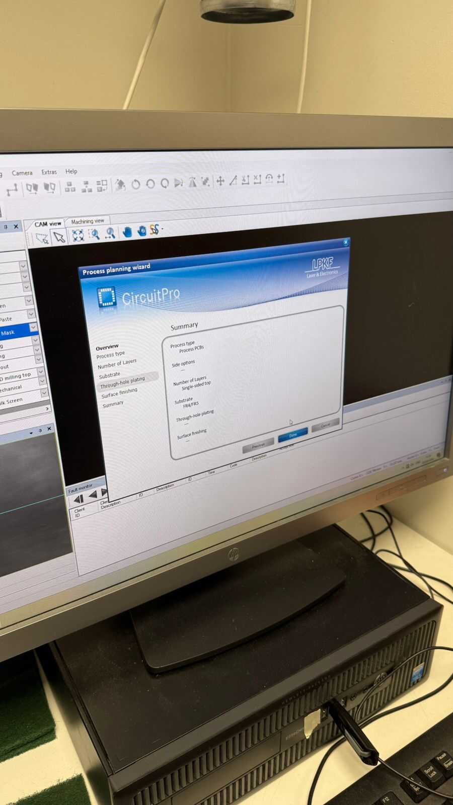
Second button:
Now we move onto the second menu, where we can now import our files.
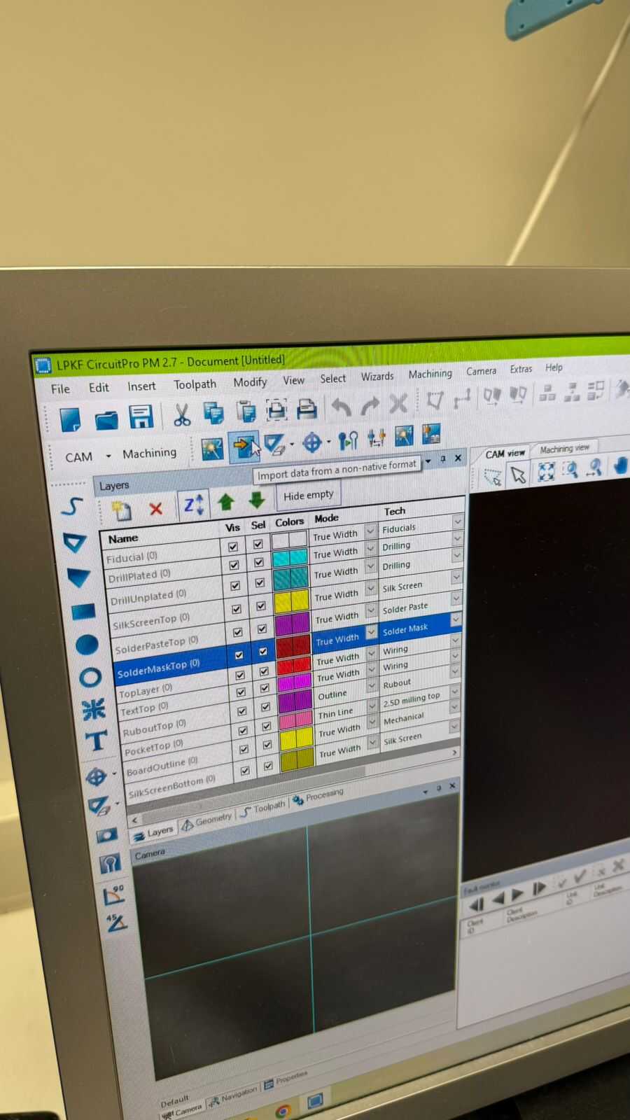
Then we import all files that we had previously exported from KiCad.
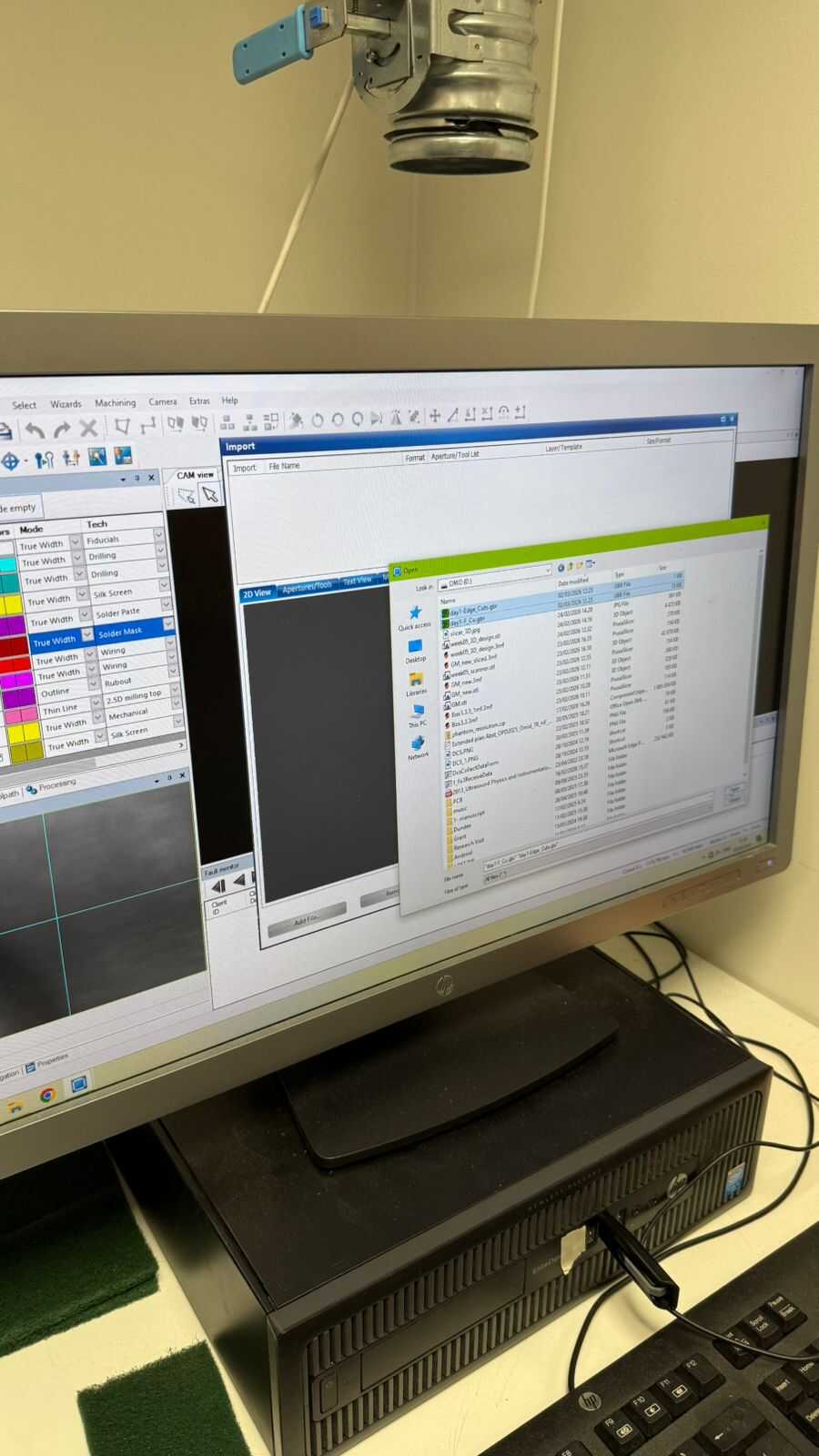
After selecting the 2 files, we need to make sure that this criteria matches otherwise it may be an issue.
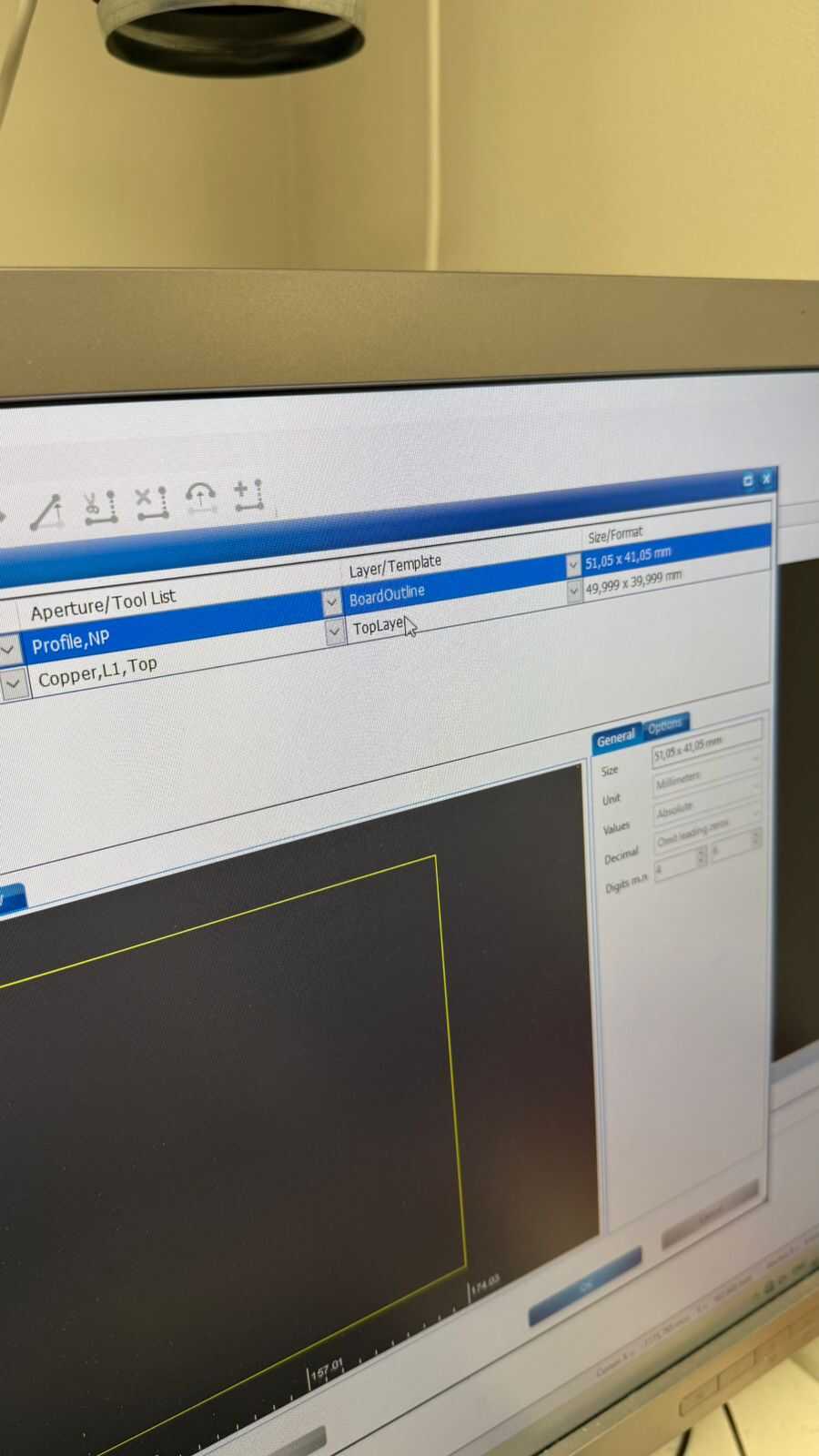
After confirming that, we click the front copper layer file to check how it is displayed on the screen.
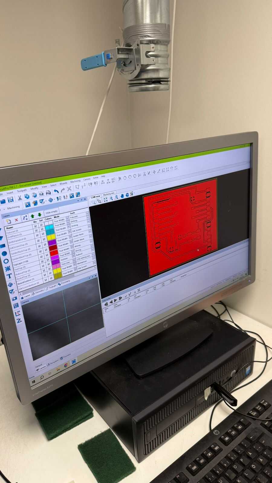
The 2 following pictures are not necessary to use for our design process, so we can skip through them.
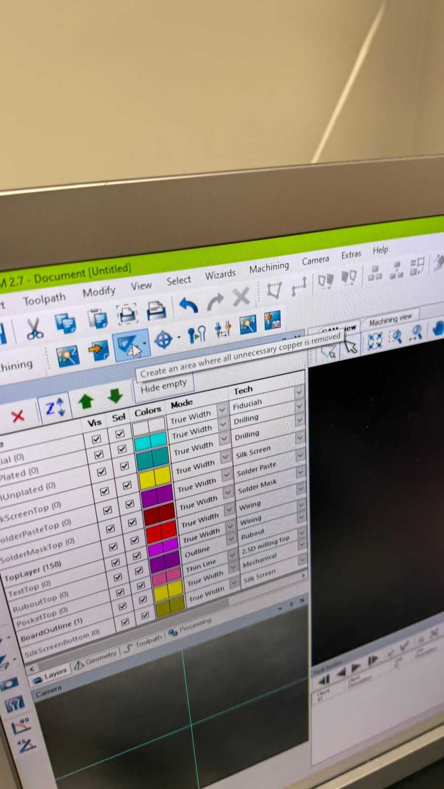
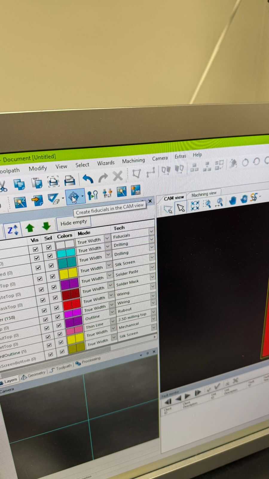
Fifth button:
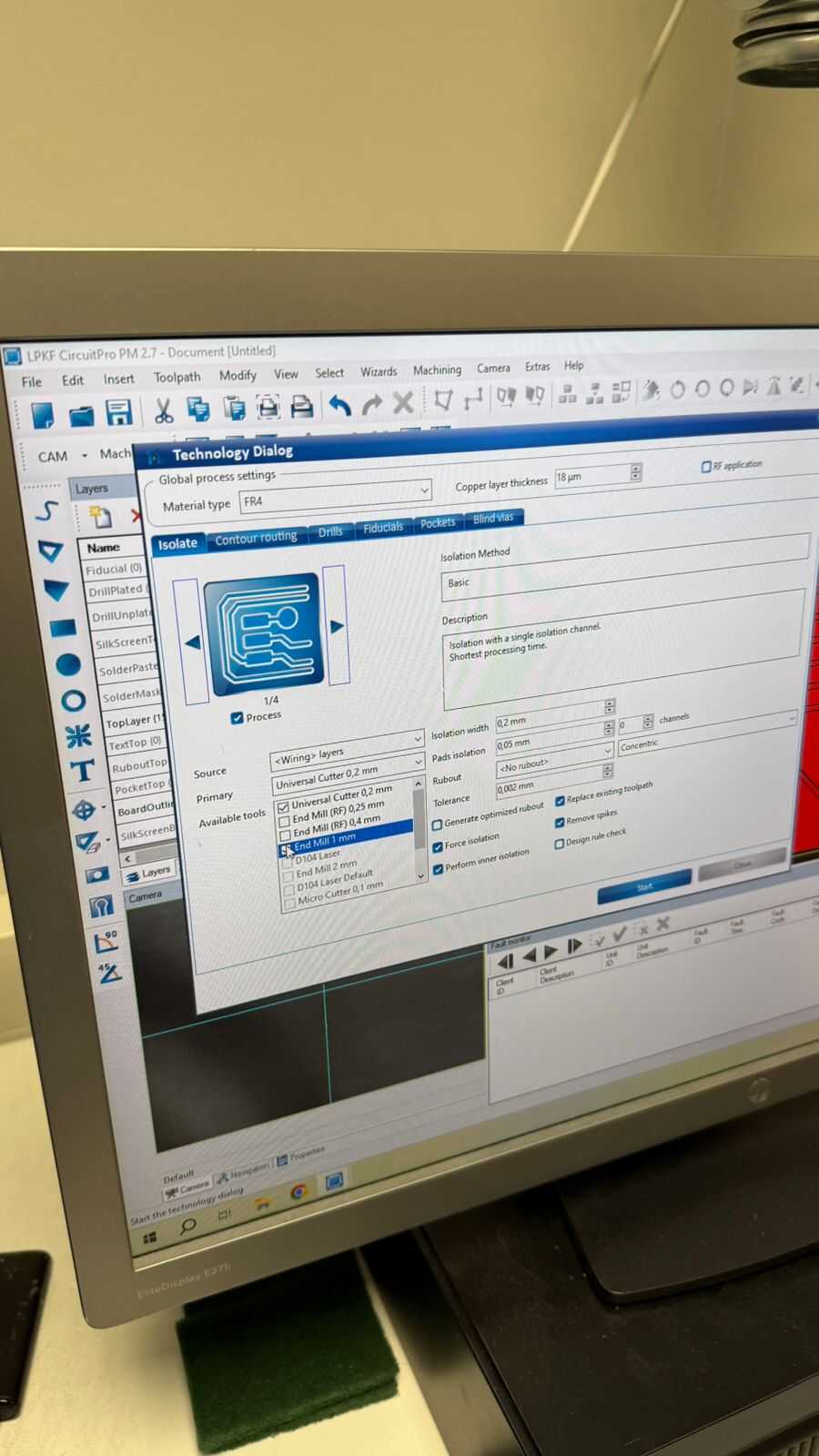
So now we are moving onto the next step which is isolation and contour routing.
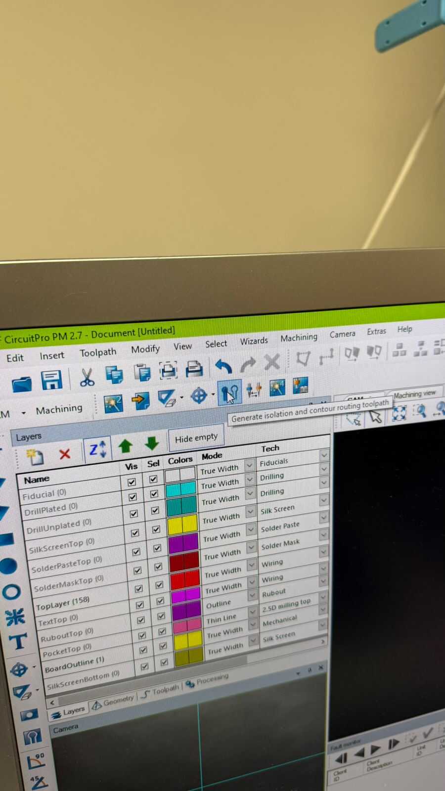
Next we have to choose the isolation process, which should be number 4 out of 4 to reduce difficulties for the soldering part later on.
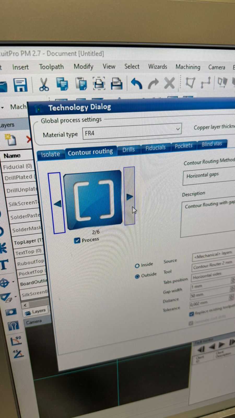
Then we choose the contour routing, which is up to you but the one shown is easier to detach when the board is finished.
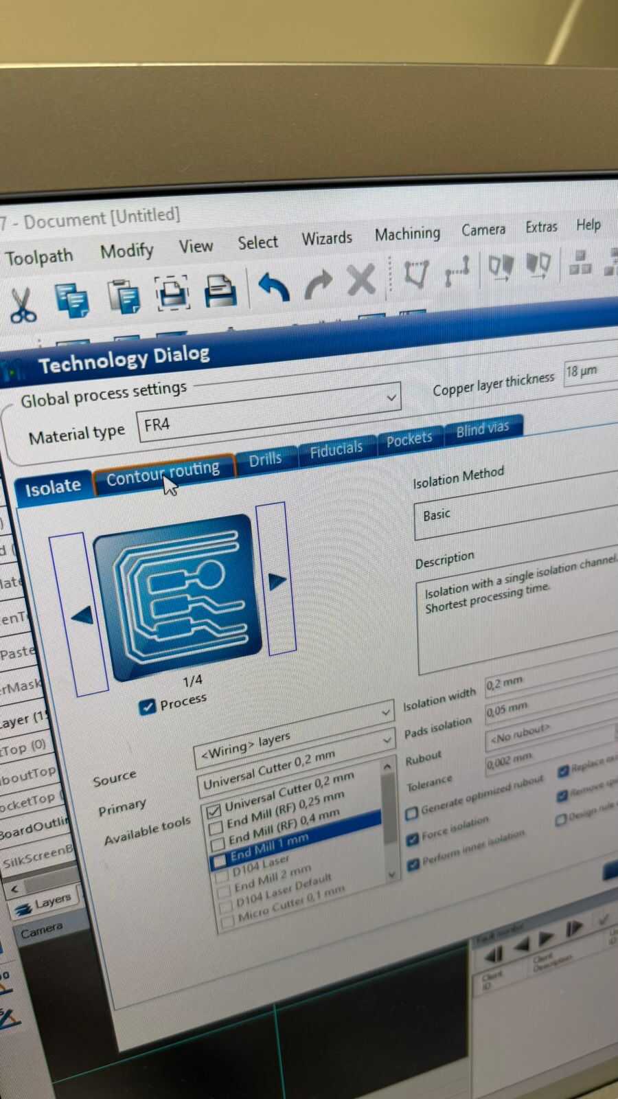
Then we choose the primary needed tools, which is universal cutter, we do not necessarily need to use end-mills, so just deselect the end-mills tools.
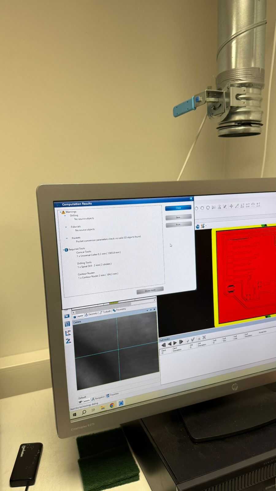
Then the confirmation window shown, just press close it.
Sixth button:
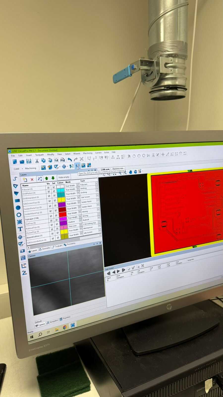
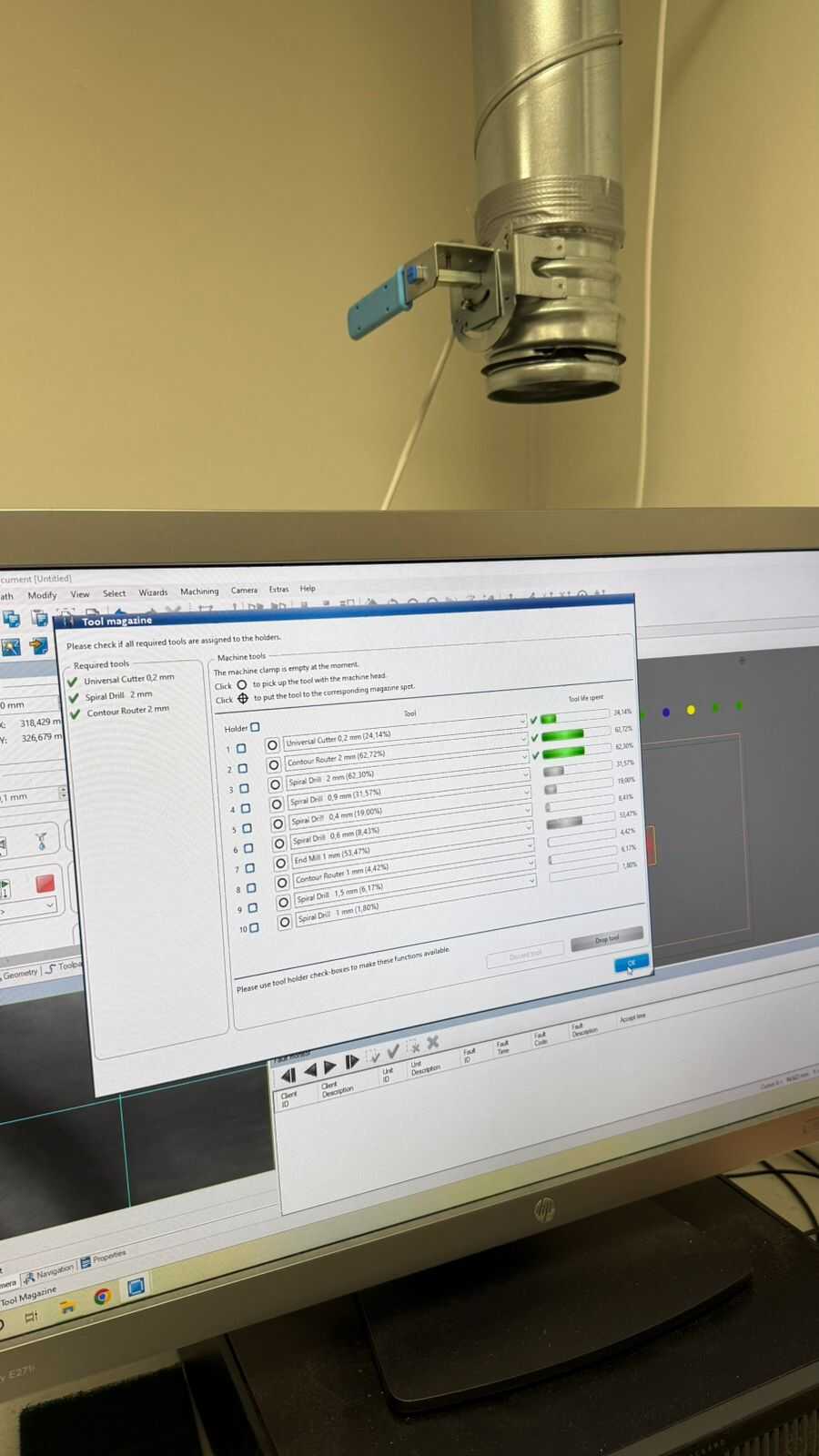
Then go to the next option, where we have to check the life expectancy of the tools, as shown in the two following pictures.
Seventh button:
Then we start the production wizard board, which is the next option in the menu bar.
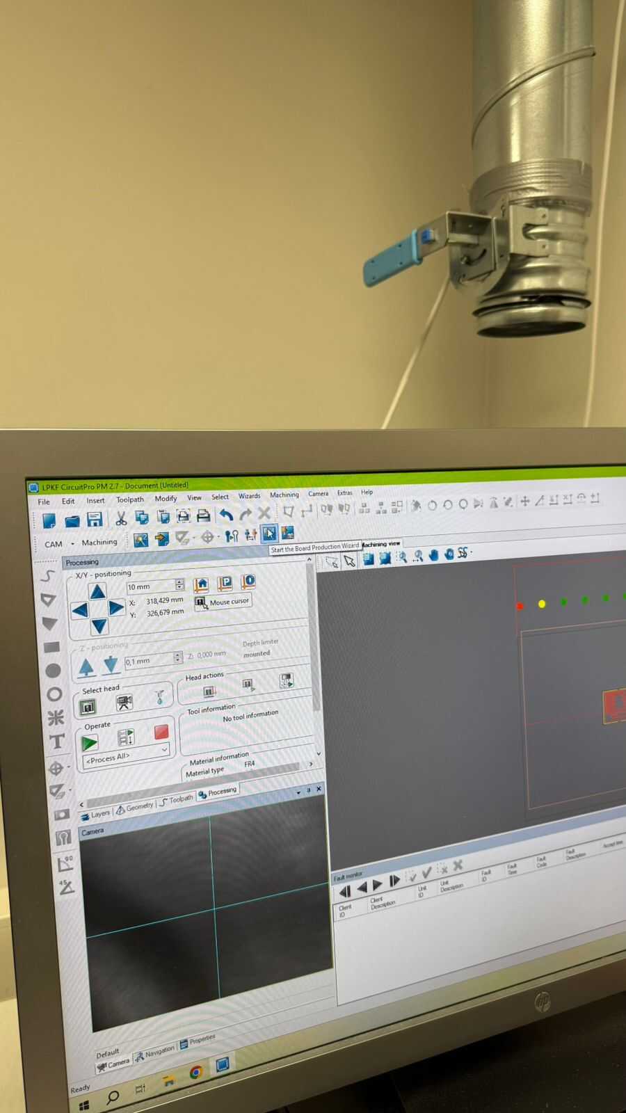
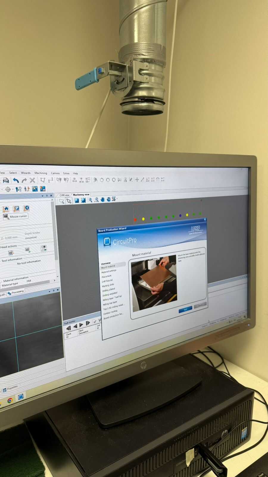
First, we have to put the material on the machine’s board, At this step, we must make sure that the material is placed perfectly inside tape and also on top of the flat surface. Then we taped the board so ensure it does not stick (because the vacuum cleaner is not working all the time during the process).
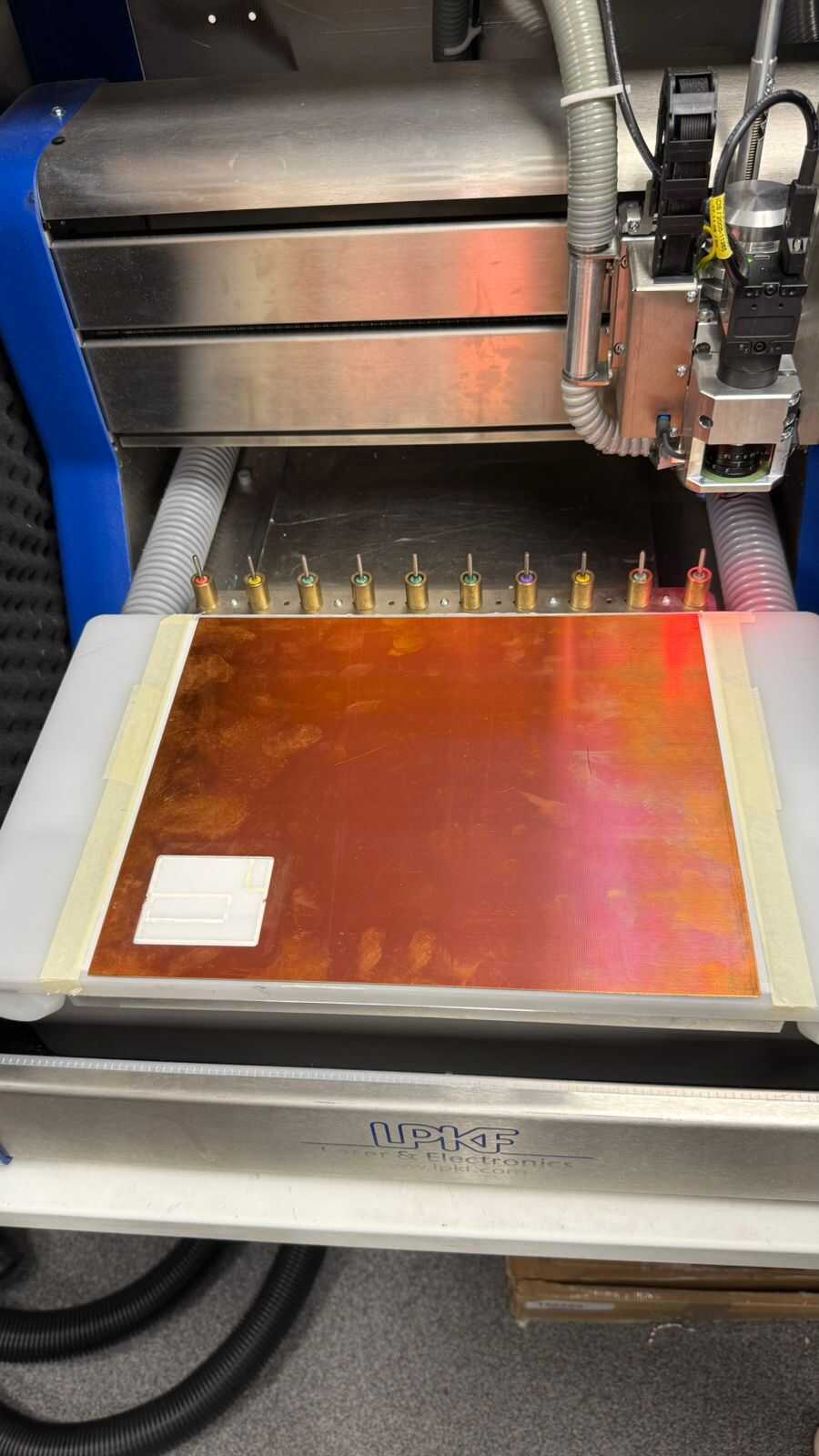
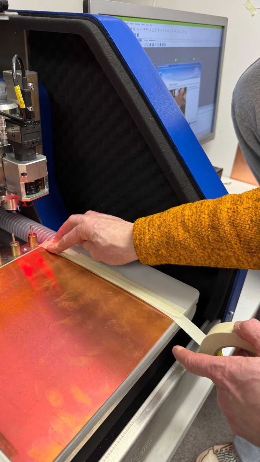
Then we start to set up the area where the machine will operate, first by set the copper thickness to 35 micro meters, and then choosing P1 and P2, which are the corners of the area.
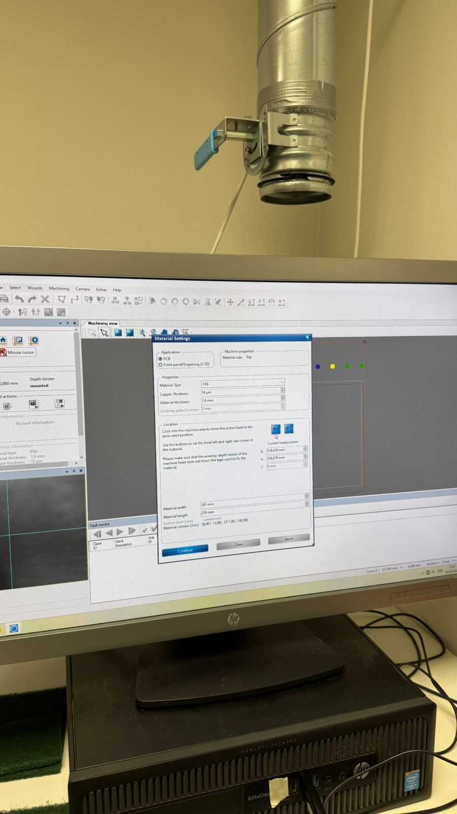
And then we adjust the nozzle so it perfectly in positions (neither outside the board nor up in the air), as shown in the 2 following pictures.
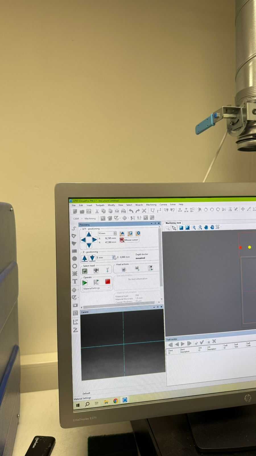
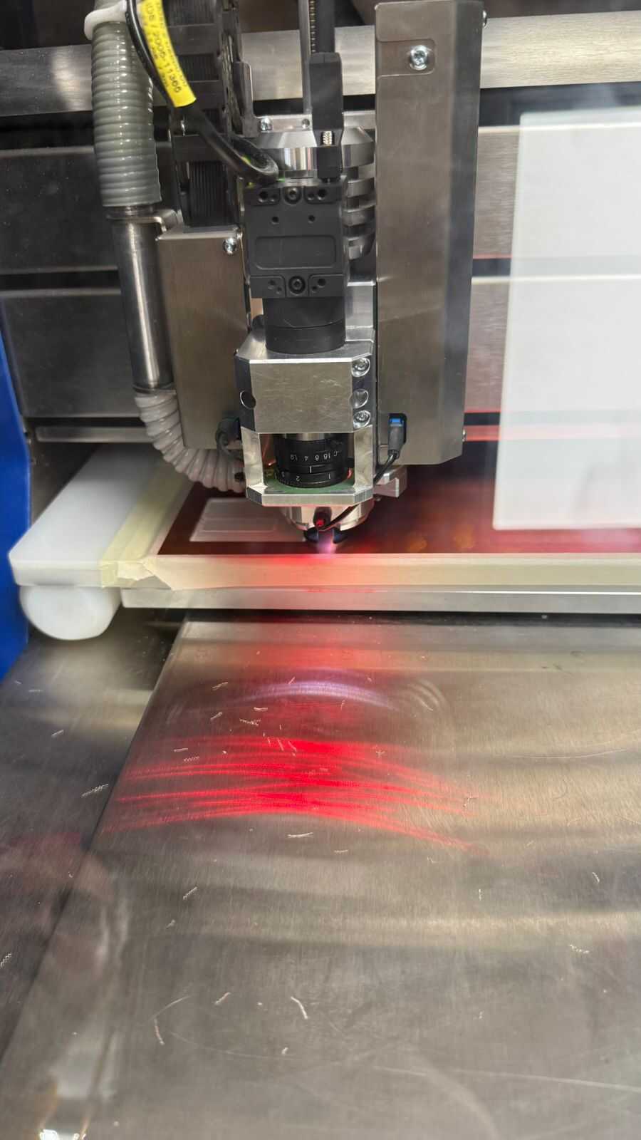
After finalizing all that we can now begin to do calibrate using a line test, which is going to be inside your work area, which is fine since it would be cut out by the contour routing. We choose the width of the line to be 0.2 millimeter.
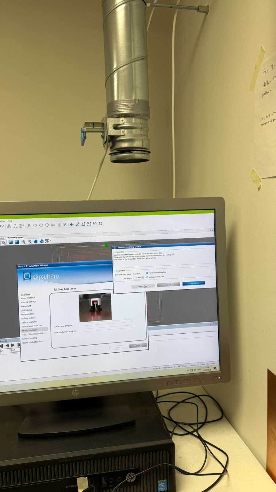
After we are shown a small confirmation popup which you can just press close on. Then we can confirm that the tools are calibrated correctly when we measure the width of the line that was made and it should be the same as what we input.
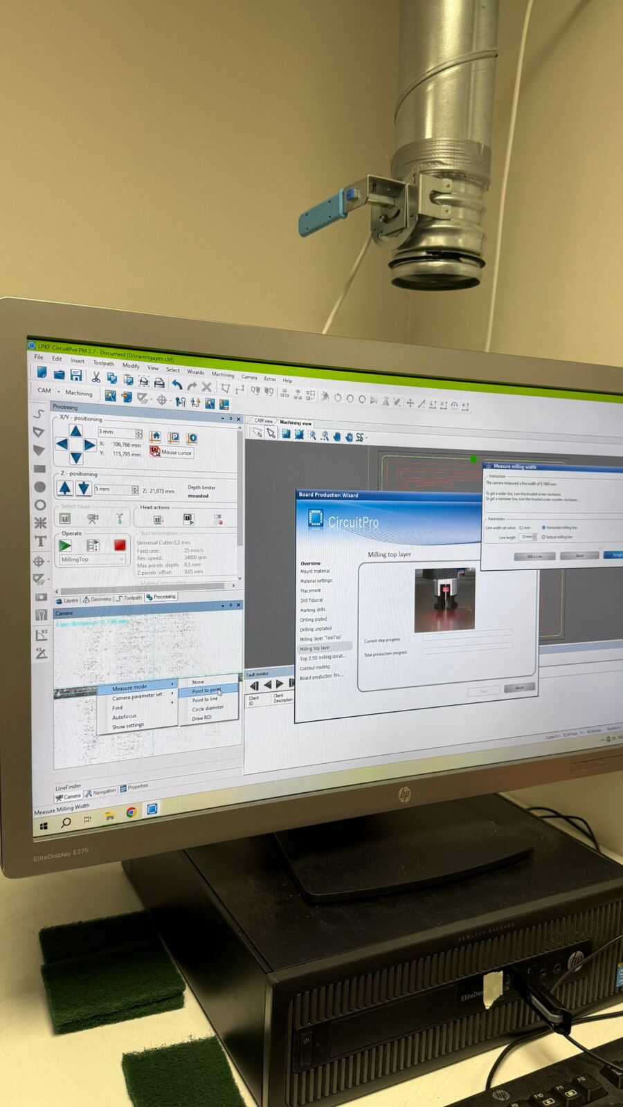
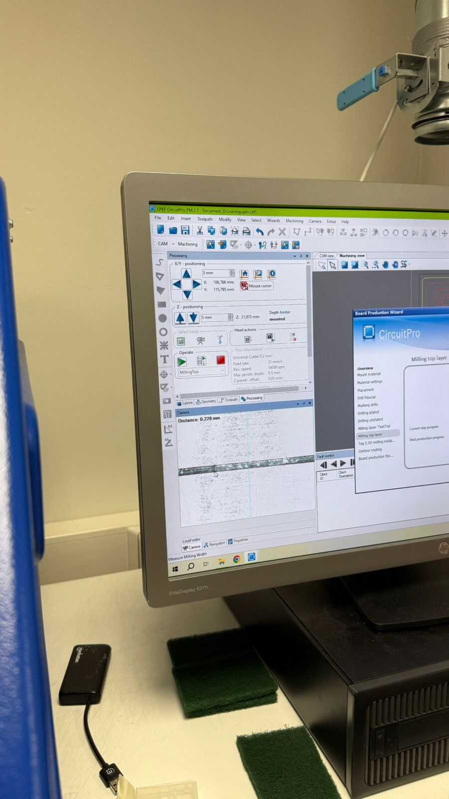
And then you can finally press start and the machine will now start making your board.
Reminder: with this machine there is possibility to have issues with the nozzle when it changes the tools, it is good measure to be aware while the machine is changing tools so you can catch it if any error happens, by opening the cover immediately.
Ordering PCB
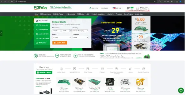
Now we are going to document the process of ordering a PCB from PCBWay, so we start with the front page of the website.
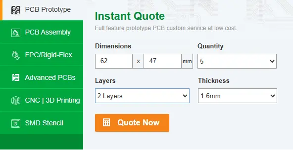
Then we have to fill in the specifications that are shown in the “Instant Quote” section, these values can be attained from KiCad’s PCB file. After that press “Quote Now”
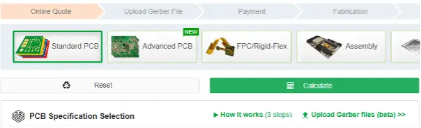
After clicking that we move onto the next page where we can more in detail specify our PCB, but to make things simpler we can just upload our gerber files.
So, the system automatically fills in all the details for us.
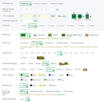
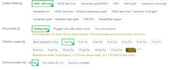
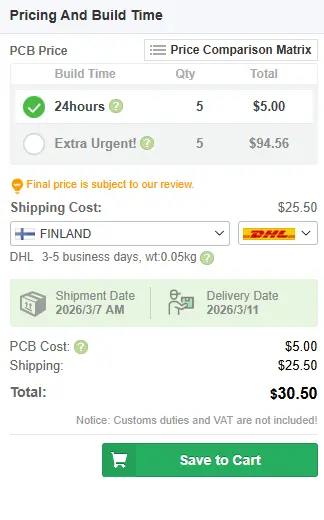
Then there are a few other criteria that can be filled, but they are not important in our case so we can neglect them. And then we can press "Calculate" to get your final price.So, then we see that the total cost of making 5 PCBs comes out to look like below.